An aircraft’s wiring may look like ordinary cable, but its job is far less ordinary. Airplane wire must carry power and signals through vibration, changing temperatures, and tight spaces. A loose connection behind a panel can matter more than its small size suggests. Every gram counts.
The differences involve more than insulation. Designers consider conductor size, weight, flexibility, shielding, abrasion resistance, and exposure to oils or cleaning fluids. They also plan how wires are routed, supported, identified, and inspected. These choices help reduce chafing, electrical interference, and failures that could be difficult to detect in flight. In practice, there is no single airplane wire for every aircraft or circuit. Requirements vary with the system, location, and aircraft design.
That distinction deserves care. “Regular wire” covers many products, and some are built for demanding industrial environments. The comparison is useful, but imperfect. Airplane wire is selected as part of a carefully engineered electrical system, not simply because it looks tougher. This article examines what makes aircraft wiring different, how materials and installation choices affect reliability, and why qualified engineering and maintenance matter. Small details matter. The wire itself is only one part of the story.
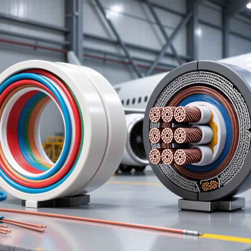
Airplane wire is not simply ordinary wire with a lighter jacket. Aircraft wiring must tolerate vibration, temperature changes, moisture, and nearby fluids while fitting into crowded structures. A wire that works well in a building may chafe against a frame or become difficult to inspect inside an aircraft bundle. Small details matter.
SAE AS50881 addresses wiring across aerospace vehicles. Its scope reaches beyond choosing conductors: it covers practices for wiring design, installation, protection, and workmanship. That means engineers consider routing, support spacing, separation from other systems, and protection at sharp edges. A clamp placed near a vibrating panel, for example, can help prevent insulation wear. The standard also supports consistent decisions across drawings, assembly, and inspection. It does not make every installation identical; the aircraft’s environment and system needs still shape the choices.
Look closely at a finished harness. Labels should be readable, bundles should be supported, and wires should not be pulled tight around bends. These are practical checks, not decoration. Still, a neat appearance can hide a poor route, so inspection must follow the installation details. Standards help, but judgment can be uneven, and that deserves a second look.
AS22759/16 aircraft wire is specified for 600 volts and a 150°C temperature rating under SAE’s AS22759 aerospace wire standard. Those numbers matter in an aircraft’s tight routes, where conductors may pass near warm equipment and share bundles. The 150°C figure describes the wire’s rated temperature limit; it does not mean surrounding air can always reach that temperature safely. Details matter.
A voltage rating is not a current rating. Current capacity also depends on conductor size, insulation, ambient temperature, and how wires are bundled. FAA Advisory Circular AC 43.13-1B gives aircraft wiring guidance that addresses installation and protection, reinforcing why a specification cannot replace careful routing and inspection. A crowded bundle can retain heat. A sharp edge can damage insulation. The rating alone will not prevent either problem.
For a technician, the practical check is not just “600 volts, 150°C.” Confirm the exact wire specification, circuit load, nearby heat sources, and installation conditions against approved aircraft data. That may feel less tidy than reading two numbers on a datasheet. It is more realistic. Even correctly rated wire can be a poor choice when its environment is misunderstood.
Airplane wire faces hotter, rougher conditions than household wiring. ETFE insulation helps because it keeps its shape under heat and resists scraping during installation and service. SAE AS22759 aerospace-wire specifications include ETFE-insulated constructions rated for continuous temperatures around 150°C, although the exact rating depends on the wire type. That margin matters near warm equipment bays, where a cable may run beside metal supports and vibrate for years.
ETFE also resists many aircraft fluids, including oils and hydraulic fluids, helping limit softening or cracking after incidental contact. SAE AS22759 sets performance and test requirements for aerospace wire, while FAA Advisory Circular 43.13-1B addresses aircraft wiring inspection and maintenance. These references make an important point: insulation performance is tested as part of a specific wire construction, not guaranteed by the polymer name alone. A mechanic still needs to check compatibility with the actual fluid and operating conditions.
Still, ETFE is not magic. A sharp clamp edge can cut it, and prolonged heat beyond its rating can degrade insulation. During inspection, look for flattened sections, abrasion near tie points, and fluid-soaked residue. Small details matter. The specification sheet should match the installation, and replacing a damaged section is safer than assuming the coating will recover.
Why Is Airplane Wire Different from Regular Wire?
Aircraft conductors face repeated bending, engine vibration, and tight routing behind panels. Fine-stranded copper helps the conductor flex without concentrating movement at one stiff point. The strands move slightly against one another as a wire curves around a bracket or connector. This can reduce fatigue risk, though it cannot prevent damage from poor support or sharp bends. More strands do not automatically mean better performance.
Copper Development Association data lists annealed copper at about 100% IACS conductivity, or 58 MS/m at 20°C. Fine stranding preserves a flexible conductor while copper carries current efficiently; wire size and insulation still matter. SAE AS50881, an aerospace wiring standard, addresses wire selection and installation practices. Vibration resistance depends on the whole installation, including clamps, bend radius, and protection at pass-throughs. A loose bundle can still rub through insulation. That detail is easy to miss.
Tips: Follow the aircraft wiring documentation for conductor type and support spacing. Inspect clamp points for looseness, chafing, and flattened insulation. Don’t assume a flexible wire can tolerate a tight bend.
| Design Dimension | Typical Aircraft Wire | Typical Building Wire | Why the Difference Matters |
|---|---|---|---|
| Conductor construction | Often made with stranded copper conductors; strand count and construction depend on the wire specification and size. | May use solid or stranded copper, depending on the cable type and intended installation. | Strands let a conductor bend more readily than a solid conductor of the same overall size. |
| Flexibility | Flexible construction helps with routing through confined aircraft spaces and around equipment. | Building wire is designed for fixed installations; solid conductors are common in some residential wiring applications. | Aircraft wiring may need to follow compact routes and connect to equipment that can move or vibrate. |
| Vibration exposure | Wire selection and installation account for aircraft vibration, routing, support, and protection requirements. | Building wiring is generally installed in structures that do not experience the same sustained engine or airframe vibration environment. | Repeated movement can contribute to conductor fatigue, especially at bends, terminations, or unsupported sections; proper routing and support are essential. |
| Copper plating | Depending on the applicable specification and temperature rating, aircraft conductors may use tin-, silver-, or nickel-plated copper. | Unplated copper is common in building wire, although conductor materials and finishes vary by product. | Plating is selected as part of a wire’s design and qualification; it should not be assumed to be identical across all aircraft wires. |
| Insulation and environment | Aircraft wire is selected for the required electrical, temperature, fluid, abrasion, and installation conditions. | Building wire is selected for its permitted building installation method and the applicable electrical code requirements. | Conductor stranding is only one part of the design: insulation and the complete wire assembly must suit the environment. |
| Connections and terminals | Terminations must be compatible with the conductor construction, wire size, and approved aircraft maintenance practices. | Terminations are chosen for the building-wire type and the device or connector being installed. | A flexible stranded conductor is not automatically compatible with every terminal; the specified connector and termination method matter. |
| Standards and selection | Some aircraft wire families are qualified to aerospace specifications such as SAE AS22759; the applicable revision and wire type must be checked. | Building wire is selected under the relevant electrical codes and product standards for its intended installation. | “Aircraft wire” and “regular wire” each cover multiple designs. Always select by the equipment documentation, installation requirements, and applicable standards. |
Note: These are general comparisons, not universal rules. Aircraft wire construction varies by specification, conductor size, and application; follow the aircraft’s approved wiring data and maintenance instructions.
AS50881 treats aircraft wiring as part of a system, not a bundle to tuck away. Its installation guidance addresses routing, support, separation, and protection from abrasion or heat. The FAA’s 2008 Aging Transport Systems Rulemaking Advisory Committee report identified chafing, contamination, and difficult inspection access as recurring electrical wiring interconnection system concerns. Those findings make physical routing choices matter: a cable crossing a sharp bracket can wear through its insulation, while a tightly packed bundle can hide damage. Neat is not always safe.
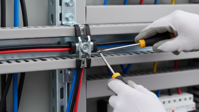
Tips: Follow the aircraft’s approved drawings and current maintenance data. Secure bundles without crushing them, protect pass-through points with suitable grommets, and keep wiring clear of moving controls, hot surfaces, and fluid lines. Preserve enough slack for vibration and servicing, but not enough to snag. Check clamps for looseness and look for flattened insulation. Small details count.
Separation needs deliberate planning, too. Keep circuits apart where the design requires it, especially when one fault could affect multiple systems. AS50881 provides the framework; the aircraft’s approved design specifies the actual route and clearances. FAA Advisory Circular 25.1701-1 also emphasizes identifying and managing EWIS throughout the aircraft. A practical check is to trace each run by hand and sight, including behind panels. That takes time. It can still miss a hidden rub point, so inspection access deserves attention during installation, not only during maintenance.
Wire size affects electrical resistance: smaller AWG numbers indicate thicker conductors and lower resistance. Values shown are nominal DC resistance for solid copper at 20°C, in ohms per 1,000 feet. Aircraft installation involves more than selecting a wire size: AS50881 addresses routing, support, and separation to help protect wiring in the aircraft environment.