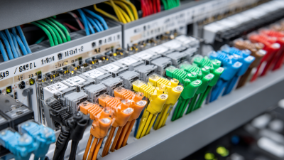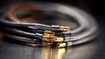
Choosing the right wire assemblies begins with understanding what they must do, where they will operate, and how they connect to the rest of a system. A cable routed beside a warm motor faces different demands from one inside a stationary control cabinet. Small details matter. Wire gauge affects current capacity and voltage drop, while insulation must suit expected heat, moisture, abrasion, and chemical exposure. Connector shape, pin arrangement, and locking style also determine whether an assembly fits and stays secure.
A useful selection process starts with the equipment’s specifications and operating conditions. Confirm the required length, conductor count, wire size, connector type, and expected electrical load. Then consider movement, vibration, installation space, and the way technicians will inspect or replace the assembly. Clear drawings and samples can help catch mismatches before production, but they do not replace checking the finished assembly against its intended application. A tidy specification can still overlook a sharp panel edge or a connector that is difficult to reach.
There is no universal best option. The right wire assemblies balance performance, durability, compatibility, and practical cost for a specific use. When requirements are unclear, consult qualified design or manufacturing professionals and verify critical details with testing. A little uncertainty is worth noting; assumptions about temperature or routing can lead to avoidable failures. Careful questions early on make the final choice more dependable.
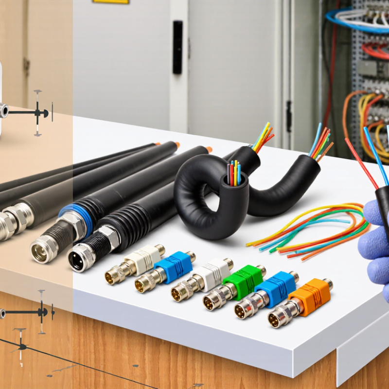
Before choosing a wire assembly, record the normal current, peak current, voltage, and operating pattern. A wire carrying 8 A continuously faces a different thermal load from one carrying 20 A for two seconds each minute. That peak duty is about 3.3% of each minute, but the repeated pulses still matter. IEEE Std 835-1994, IEEE Standard Power Cable Ampacity Tables, shows how allowable current depends on conductor size, insulation, and installation conditions. Treat its ampacity data as a starting point, not a direct rating for a finished assembly; connectors, bundling, ambient heat, and enclosure space can change performance.
For example, a cable routed beside a warm motor may shed heat less effectively than the same cable in open air. Check the assembly’s insulation temperature rating and the connector’s current rating, then consider both together. A short peak can cause trouble when cycles repeat or cooling time is limited. I’ve seen duty-cycle assumptions get overlooked. They are easy to miss.
Tips: Write down the load profile over a full operating cycle. Include startup surges, idle periods, and the hottest expected ambient temperature. If measurements are uncertain, leave margin and validate the assembly under representative conditions.
Choosing a wire assembly starts with the conductor, not the insulation’s outside diameter. ASTM B258 gives 12 AWG copper a nominal bare diameter of about 2.05 mm and a cross-sectional area of 3.31 mm². Those figures describe the metal only. Insulation and stranding make the finished wire thicker, so check the cable drawing before sizing a connector or grommet. A wire that fits on paper may snag at a tight bend.
Current capacity needs context. NFPA 70 (2023), Table 310.16, lists 12 AWG copper at 20 A for 60°C insulation, 25 A at 75°C, and 30 A at 90°C. These values assume specified installation conditions, including 30°C ambient temperature; terminal ratings and adjustment factors can lower the usable limit. One detail is easy to miss. A warm enclosure, several bundled conductors, or a long run can change the design choice. Check the actual route, insulation rating, and load before selecting the assembly. The gauge is a useful starting point, not a complete answer.
Choosing a wire assembly starts with the conditions it will actually face. Check the circuit voltage, then select insulation rated for that voltage or higher.
UL 758 covers appliance wiring materials, including constructions rated for 600 V and 105°C. Those figures are not interchangeable: 600 V describes an electrical rating, while 105°C is a temperature limit for specified conditions.
Read the exact wire style and component documentation before specifying an assembly. A label alone can leave questions unanswered.
Heat deserves close attention. A cable routed beside a warm motor may experience a different temperature than one in open air. Bundling, enclosure airflow, and nearby heat sources can also affect operating conditions.
Choose insulation whose temperature rating suits the expected environment, with an appropriate margin where practical. Don’t assume a 105°C rating means every finished assembly can run continuously at that temperature; terminals and other parts may have lower limits.
Small details matter. Conductor size, flexibility, and bend radius also affect fit and performance. I have seen neat-looking layouts become difficult to service when wires were too stiff or crowded. That is easy to overlook.
Verify the complete assembly against its intended use, and ask the supplier for supporting specifications when a rating or construction detail is unclear.
When selecting wire assemblies for wet environments, match the seal rating to the exposure. IEC 60529 defines IP67 as dust-tight protection plus resistance to temporary immersion. Its IPX7 test uses water at a defined depth of 1 meter for 30 minutes under specified conditions. That is a test limit, not a promise of unlimited underwater operation. A harness may still be vulnerable at cable entries, splices, or unmated connectors.
Tips: Check the rating for the complete, correctly assembled connection. Confirm whether it applies when mated, and inspect seals for cuts or pinching. If the cable moves often, test a sample after flexing it. Small details matter.
IP67 can suit equipment exposed to brief flooding, washdown splash, or accidental drops into shallow water. But pressure, temperature changes, detergents, and repeated immersion can exceed the standard test conditions. One detail is easy to overlook: an IP rating describes enclosure protection, not resistance to every chemical or mechanical stress. Ask suppliers for the test conditions and verify the finished assembly in its actual installation. A rating on one connector alone may not cover the whole wire assembly.
| Exposure or Use Case | Relevant Ingress Protection Guidance | Wire Assembly Selection Considerations | Verification Before Use |
|---|---|---|---|
| Indoor equipment with no expected water exposure | Choose an enclosure protection level based on the required protection from solid objects and dust; water protection may not be necessary. | Confirm the cable insulation, temperature rating, flexibility, and connector style suit the equipment and installation environment. | Check the full assembly specification and the equipment manufacturer’s installation instructions. |
| Rain, splashes, or water spray | IEC 60529 IPX4 addresses splashing water from any direction. IPX5 and IPX6 address water jets at different test severities. | Use components and assembled connections rated for the expected spray exposure. Consider orientation, drainage, and whether water can track along the cable. | Confirm that the rating applies to the connected assembly, including mating connectors, seals, and cable entries. |
| Temporary immersion, such as occasional submersion during handling or cleaning | IPX7 covers temporary immersion under the IEC 60529 test conditions, commonly described as immersion up to 1 m for 30 minutes. | Select a complete assembly designed for temporary immersion. A connector’s rating alone does not establish that the cable entry or the entire assembled connection is protected. | Check the manufacturer’s stated immersion conditions, mating requirements, and any limitations on repeated or dynamic immersion. |
| Prolonged or deeper immersion | IPX8 applies to continuous immersion under conditions agreed between the manufacturer and user; the conditions are not universally fixed at 1 m. | Specify the actual operating depth, duration, water type, temperature, and pressure when selecting the assembly. | Obtain documented test conditions for the exact assembly and confirm compatibility with the intended installation. |
| High-pressure, high-temperature washdown | IPX9 addresses high-pressure, high-temperature water jets under the applicable IEC 60529 test method. | Choose an assembly specifically suitable for the washdown conditions; immersion protection alone does not demonstrate resistance to these jets. | Verify the tested rating for the complete configuration and follow specified mounting and cleaning instructions. |
| Dusty environment combined with water exposure | The first IP code digit describes protection against solid-object access and dust; the second digit describes water protection. For example, IP67 combines a dust-tight first digit with IPX7 water protection. | Match both parts of the IP code to the real exposure. Consider abrasion, chemical contact, vibration, and cable bend requirements separately. | Confirm the complete IP code and that testing covers the installed connector, seals, cable gland, and enclosure interface. |
Choosing a wire assembly means checking more than conductor size and connector fit. The termination often determines whether the assembly performs reliably in service. Use IPC/WHMA-A-620 as a workmanship reference, and confirm the required revision and acceptance class in the purchase documents. Requirements may differ by class and application.
Look closely at crimped terminals under good lighting. Check that the conductor is positioned correctly, strands are not cut or loose, and insulation support is present without covering the contact area. For soldered connections, inspect wetting, clearance, and signs of bridges or excessive solder. Small defects matter. A joint can appear neat while hiding a weak crimp, so visual checks should follow documented criteria. Use pull testing when the inspection plan calls for it, with defined sampling and limits.
Keep inspection records tied to the assembly lot, tooling, and applicable criteria. That makes recurring issues easier to trace. Even experienced inspectors may interpret borderline workmanship differently; clear photographs and agreed examples can reduce uncertainty. A checklist helps, but it is not perfect. Pair it with trained review, calibrated tools, and a process for resolving uncertain findings before assemblies are accepted.